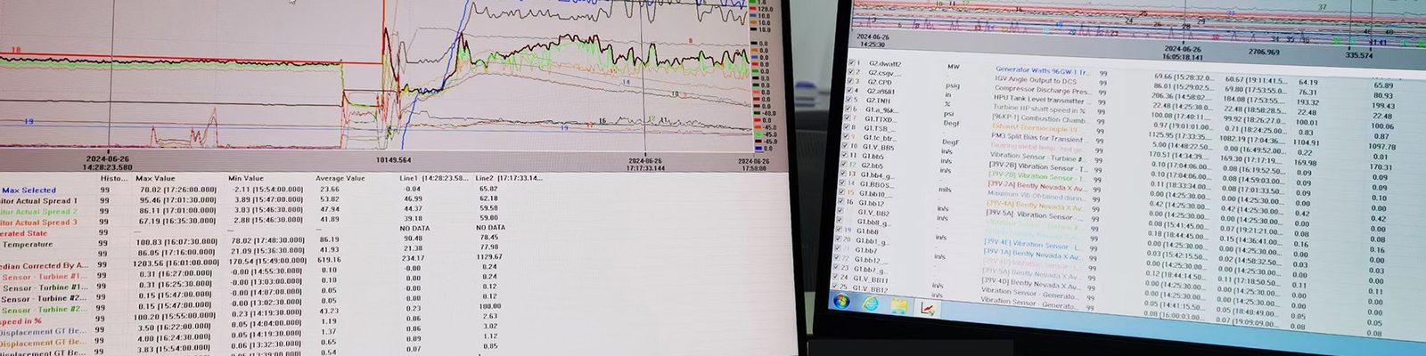
Products / GGP engineered applications

Products developed around real control-system failure modes.

Technical data, application boundaries and the engineering inputs required to apply each product correctly.

LC-TH DC current transducer · 4–20 mA output

Through-hole low-current transducer

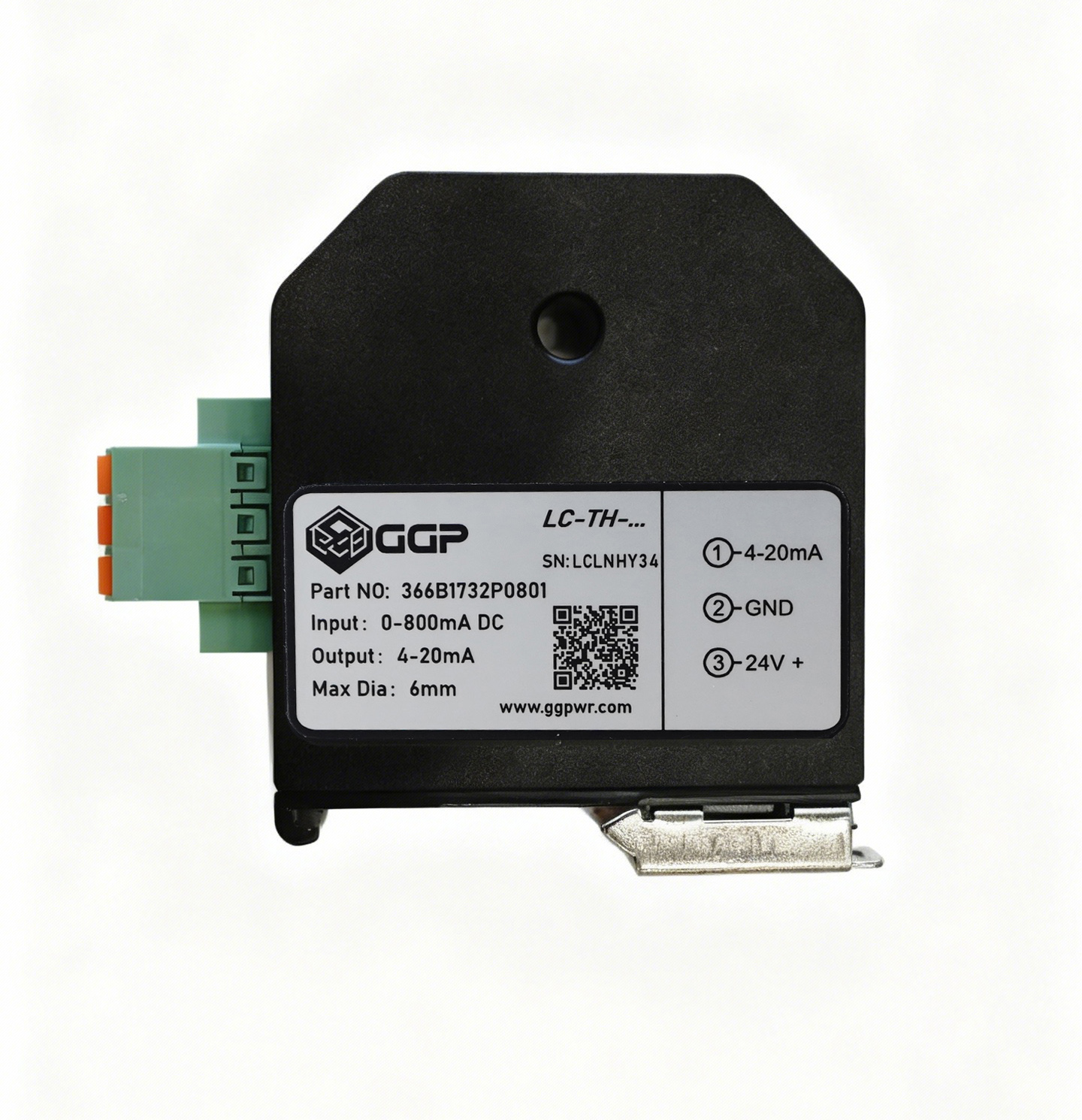
The 366B1732 measures low DC current without opening the primary conductor path. The conductor passes through the 6 mm aperture, while the isolated transducer converts the selected 0–100 to 0–800 mA input range into a standard 4–20 mA signal for control-system monitoring, alarms and trending.

366B17320–100 to 0–800 mA DC4–20 mA35 mm DIN rail
0–800 mAavailable DC range family
4–20 mAisolated analog output
2500 VDCrated isolation voltage
300 ms90% step response
Technical specifications2 data groups

Measurement

Model family
366B1732P0101 to 366B1732P0801
Input ranges
0–100 / 200 / 300 / 400 / 500 / 600 / 700 / 800 mA DC
Overload
Up to 3 × nominal input current
Output
4–20 mA; maximum output < 25 mA
Output load
< 300 Ω
Transmission error
< ±1% of input range final value at 25 °C
Linearity error
< ±1% of input range final value at 25 °C

Electrical & mechanical

Supply
24 VDC nominal; 20–30 VDC operating range
Consumption
30 mA + output current; < 1.5 W at maximum conditions
Conductor opening
6 mm through-hole
Isolation
2500 VDC rated insulation voltage
Dimensions
60 × 60 × 20 mm
Mounting
35 mm DIN rail
Environment
−10 to +65 °C; IP20
Connections
Spring-cage; AWG 24–14
The published 366B1732 range family covers 0–100 through 0–800 mA DC. Each device is supplied for one selected nominal range.
Application engineeringdetails, uses & required inputs

Engineering details

Preserve the primary circuit

The live conductor passes through the aperture and remains electrically continuous. Installation checks conductor access, insulation, bend radius and panel clearance without placing the transducer in the command path.

Match the input range to the real circuit

The order code is selected from the measured normal current and the diagnostic range required. A correctly selected range improves useful resolution and alarm discrimination.

Bring the signal into existing control hardware

The isolated 4–20 mA output can be mapped to an available analog input for indication, alarms and trend recording, with scaling and channel documentation completed during commissioning.

Applications

Signal-level DC ground-fault monitoring
Solenoid and relay-coil monitoring

Monitor low-current DC coils for loss of current, abnormal magnitude or gradual deviation while retaining the original control wiring.

Protection and auxiliary circuits

Add current evidence to commands and feedbacks in trip, hydraulic, pneumatic and balance-of-plant circuits.

Single-channel retrofit monitoring

Use the compact DIN-rail device where one or a small number of circuits require dedicated isolated analog outputs.

Application details to confirm
  • Circuit voltage and measured normal DC current
  • Required input range and alarm objective
  • Conductor diameter and panel clearance
  • Available 4–20 mA input and scaling
  • Supply and DIN-rail arrangement
Compatibility & application boundary

366B1732 is the DC-input member of the LC-TH analog-output family. Select the exact P0101–P0801 order code from the required current range, then confirm conductor diameter, 4–20 mA receiving input, supply, isolation and available panel space.
LC-TH MC / EMC · RS-485 Modbus RTU

24-channel low-current collector with CT

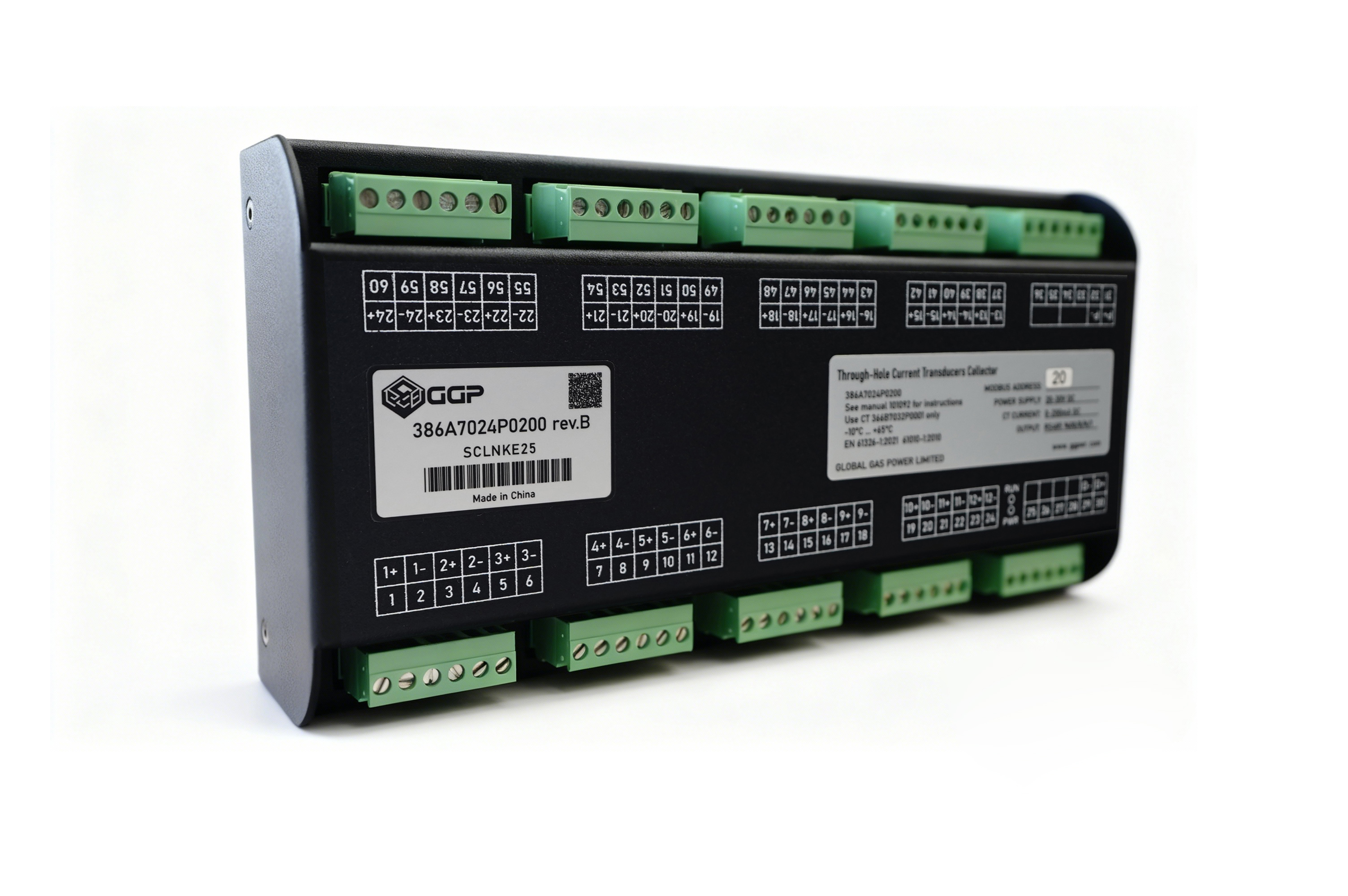
The 386A7024 and 386A9024 combine a 24-channel collector with matched through-hole current transformers. Each conductor passes through its CT, allowing the collector to acquire low-current signals without interrupting the original circuit and transmit channel data through RS-485 Modbus RTU for HMI, historian and diagnostic use.

24 channels24-bit ADCMatched through-hole CTsRS-485 Modbus RTU
24measurement channels
24-bitcollector ADC
2500 VDCrated isolation voltage
300 ms90% step response
Technical specifications2 data groups

Collector / 386A7024 & 386A9024

386A7024 ranges
0–100 / 200 / 300 / 400 / 500 / 600 / 700 / 800 mA
386A9024 range
0–20 mA enhanced measurement
Channels
24
Output
RS-485; Modbus RTU
Baud rates
1200 to 57600 bps; 9600 bps default
Supply
24 VDC nominal; 20–30 VDC operating range
Consumption
≤ 20 mA; ≤ 0.5 W
Linearity
< ±1% of range final value at 25 °C
Dimensions
225 × 118 × 50 mm; 35 mm DIN rail
Environment
−10 to +65 °C; IP20

Matched current transformers

7024 CT
LC-TH-C1000 / 366B7032P0001; 0–1000 mA DC
9024 CT
LC-TH-C0020 / 366B9032P0001; 0–20 mA DC
Overload
Up to 3 × nominal current
Conductor opening
8 mm
Connection
5 m loose-wire lead
Dimensions
29 × 26 × 13 mm, excluding lead
The 386A7024 order code selects one calibrated standard range. The 386A9024 is the enhanced 0–20 mA configuration and requires its corresponding CT.
Application engineeringdetails, uses & required inputs

Engineering details

Keep all 24 channels outside the command path

Each conductor remains intact and passes through a matched CT. Channel allocation, cable routing and CT orientation are documented before installation.

Select the collector and CT as a matched pair
Build a 24-channel diagnostic baseline

Commissioning maps channel numbers to circuits, records normal current signatures and verifies Modbus addressing, scaling, update rate and receiving-system displays.

Correlate current with command and feedback

Applications

DC ground-fault circuit localization
Multi-channel solenoid monitoring

Monitor banks of trip, hydraulic or pneumatic coils from a single collector while preserving the existing wiring topology.

Dormant-channel and discrepancy detection
HMI and historian integration

Publish 24-channel current values through Modbus RTU for alarms, trend review and maintenance records.

Application details to confirm
  • Circuit list and required 24-channel allocation
  • Measured current range for each circuit
  • Required collector and matched CT family
  • RS-485 address, baud rate and Modbus mapping
  • Panel space, routing and receiving-system interface
Compatibility & application boundary

Use 386A7024 with LC-TH-C1000 / 366B7032P0001 CTs for the 0–100 to 0–800 mA collector ranges. Use 386A9024 with LC-TH-C0020 / 366B9032P0001 CTs for the enhanced 0–20 mA range. Confirm range, CT type, channel allocation, RS-485 settings and receiving-system scaling together.

High-temperature fire detection for turbine hot zones

HeatShield 500

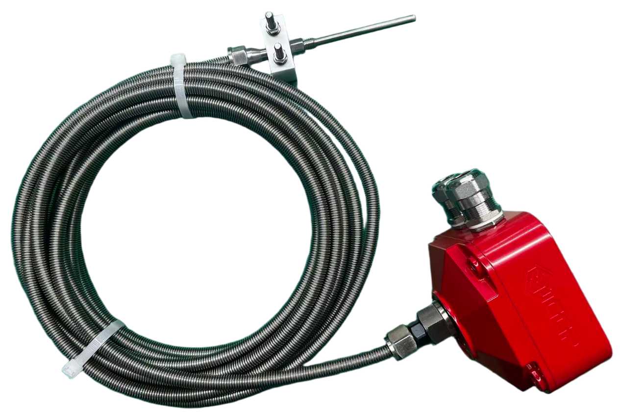
HeatShield 500 separates the PT1000 sensing element from the electronics housing through a high-temperature corrugated steel hose. This allows the detector body to remain outside the hottest zone while the sensing element monitors turbine enclosures, exhaust ducts, test benches and similar industrial areas.

50–450 °C setpointPT1000IP669 m remote sensor
0–450 °Cstatic measuring range
−20 to +600 °Csensor-element environment
9 mcorrugated steel hose
1 smeasurement cycle
Technical specifications2 data groups

Detection

Measuring principle
PT1000
Alarm setpoint
Configurable from 50 to 450 °C
Response modes
Rate-of-rise with fixed-temperature backup, or fixed-temperature only
Accuracy
2% of full range or 2 °C, whichever is higher
Ready after power-on
Approximately 30 seconds
Local indication
Green normal / red alarm / yellow fault
Test
Magnetic reed-switch test initiation

Electrical & mechanical

Supply
14–29 VDC rated band; 10–30 VDC operating range
Current
Approx. 30 mA at 24 VDC with alarm and fault relays energized
Outputs
Dry contacts; max. 60 VDC / 25 VAC, 1 A
Housing
Die-cast aluminum; approximately 2 kg
Protection
IP66
ATEX marking
II 2 G Ex db IIC T6 Gb / II 2 D Ex tb IIIC T80 °C Db
EU type examination
ECM 25 ATEX-B CS86
Hose
9000 ± 200 mm; minimum bend radius 120 mm
Cable entries
M16; 5–8 mm cable
Detector housing: −20 to +90 °C. Corrugated hose: −20 to +500 °C. Sensor element: −20 to +600 °C. The configured operating setpoint remains within 50–450 °C.
Application engineeringdetails, uses & required inputs

Engineering details

Separate electronics from the highest-temperature zone

The remote sensing element is thermally decoupled from the housing by the armored hose. Installation engineering confirms detector-body location, sensor placement, mechanical support and the minimum bend radius along the complete route.

Supervise the sensor circuit

The detector monitors the sensing element for wire break and short circuit. Alarm, fault and normal states are mapped to the receiving fire panel and control-system indications before commissioning.

Verify response, reset and cause-and-effect

A latched alarm is reset by a brief supply interruption. Functional testing covers normal, alarm and fault indications, output contacts, panel annunciation, trip interfaces and the approved cause-and-effect matrix.

Plan retrofit compatibility as a complete loop

Mechanical dimensions and signal interfaces are designed for replacement applications including 397A7510 references. The installed loop voltage, wiring, end-of-line arrangement, mounting and protection logic are still verified for each project.

Applications

Gas turbine enclosure hot zones

Detect rapid heat development where conventional detector electronics cannot be located close to the monitored surface.

Exhaust ducts and industrial test benches

Place the remote sensing element in the high-temperature area while maintaining access to the detector housing for inspection and testing.

Legacy high-temperature detector replacement

Use a documented retrofit process that confirms mechanics, loop behavior, panel interfaces and cause-and-effect before removing the installed detector.

Application details to confirm
  • Installed detector and fire-panel references
  • Loop voltage, current and end-of-line arrangement
  • Mounting, hose route and environmental conditions
  • Fire-zone and cause-and-effect documentation
  • Required alarm, trouble, trip and reset interfaces
Compatibility & application boundary

Designed for high-temperature replacement applications including 397A7510 references. Models 397A8510 and 397A9510 have documentation covering ATEX 2014/34/EU, EMC 2014/30/EU, RoHS and IP66, including EU-type examination ECM 25 ATEX-B CS86. Confirm the exact model marking, supplied documentation, local requirements, fire-panel loop and protection logic for each destination.

Industrial data collection and reporting

EGD Historian

A configurable platform for direct, high-speed Ethernet Global Data (EGD) collection, compression, historical query and reporting without an OPC forwarding layer. The system is engineered around the actual controller nodes, exchange definitions, point count, time source and retention objective.

High-speed collectionRAID storageNTP synchronizationExport-ready
EGDnative acquisition context
RAIDstorage resilience option
NTPtime synchronization
Multi-formatdata export
Technical specifications1 data group

Application engineering

Inputs
Controller nodes and EGD exchange definitions
Acquisition
Point-specific rate and collection scope
Storage
Retention and compression configured to objective
Views
Historical query, trend and text-based review
Time
Defined NTP source and synchronization checks
Interfaces
Network access and export requirements
Application engineeringdetails, uses & required inputs

Engineering details

Define the evidence before collecting everything

Point selection and sample rate follow the operating questions the historian must answer. Fast protection or sequencing signals are separated from slower condition and performance data.

Protect timestamp quality

Controller, HMI and historian time sources are reviewed together so alarms, events and trends can be correlated during trip or performance analysis.

Validate recovery and export

Commissioning covers live acquisition, historical queries, retention, storage health, user access and representative exports—not only the appearance of a trend screen.

Applications

Trip and event analysis

Preserve fast, time-aligned operating evidence for post-event review and comparison with alarms, events and sequence logic.

Operator and maintenance trending

Provide repeatable views for recurring symptoms, gradual deviation and before / after comparison following a maintenance or control change.

Application details to confirm
  • Controller nodes and EGD exchange definitions
  • Point count, collection rate and analysis objective
  • Retention, storage and export requirements
  • Network addressing, access and security constraints
  • Time source and existing historian interfaces
Compatibility & application boundary

Designed for EGD-based control environments. Collection scope, network boundaries, cybersecurity requirements and any existing historian interfaces are confirmed during engineering.

Parts & platform support

Control hardware, HMIs and field instruments.

Mark V / Mark VI / Mark VIe / Mark VIeSEX2100e / EX2100LS2100e / LS2100HMIs, networks & historian hardwareKey turbine instruments
Search technical parts list ↗